

 en
 English
 Español

At a water treatment plant, a technician slips a cheater bar over the lever of a 10-inch butterfly valve and pulls. The valve moves, but the lever bends and the pipe bracket flexes. That is where a geared valve stops being a convenience and becomes a safety requirement. A geared valve—often called a gear-operated valve—is a quarter-turn valve fitted with a manual gear operator. The gearbox multiplies handwheel torque, holds position without a brake, and turns a high-effort task into a controlled one. Specify one when calculated torque exceeds comfortable lever effort, when the valve must stay put under vibration, or when the installation needs a declutchable manual override for an actuator.
Content
What a geared valve actually is
Strip away the catalog language and a geared valve is three components: the valve, the mounting interface, and the gear operator. The valve can be butterfly, ball, or plug type, as long as it is quarter-turn. The operator is usually a worm gearbox with a handwheel on the input shaft and a hollow output bore that fits the valve stem. The interface is defined by ISO 5211—flange size, stem dimensions, and bolt pattern—so the gearbox, valve, and accessory brackets share a common mounting standard.
Worm gears dominate manual valve service because the lead angle can be made self-locking. The valve cannot back-drive the handwheel when the operator lets go. That matters on a 12-inch butterfly valve in a pump discharge line: the disc sees dynamic torque, and a non-locking lever can drift or snap back. A self-locking gear operator holds the set position until the next deliberate input.
Geared valves also change the operator's relationship with the valve. A handwheel can be turned from a safe standing position, the ratio smooths the breakaway peak, and the position indicator gives a clear open/closed reference. The trade-off is speed—multiple handwheel turns for 90 degrees—and cost. That is why levers still dominate small, low-torque service. For a component-level explanation, see this guide to what a part-turn gearbox is and how it works.
When a lever is enough—and when it is not
Lever handles are fast, cheap, and easy to read. On a 2-inch or 3-inch butterfly valve with clean fluid and low differential pressure, a lever is usually right. Trouble starts when lever length is fixed while required torque rises with valve size, line pressure, and fluid condition. Operators then add a pipe extension. That is not a torque solution; it is a load path into the stem, the lever, and the operator's shoulder.
A gear operator changes the ratio. A 4:1 worm gear turns 2,000 N·m at the valve stem into 500 N·m at the input, before efficiency losses. Handwheel diameter then sets rim force. If rim force is still above the ergonomic limit, the next step is a larger ratio or a different operator type—not a longer cheater bar.
Common sizing practice uses the valve manufacturer's breakaway torque at maximum differential pressure, then applies a safety factor. Clean service often uses 1.5; slurry, high-temperature, or frequent cycling may use 2.0 or higher. The gearbox output rating must exceed that calculated torque, and handwheel input force must stay within the project limit. European sizing practice under EN 12570 sets limits for manual operating elements; many specifications translate that into a handwheel force cap around 360 N. Check the project specification, because the cap can be lower.
| Feature | Lever handle | Gear operator |
|---|---|---|
| Operating effort | Direct 1:1; limited by operator strength | Multiplied by gear ratio; handwheel force can be controlled |
| Position holding | Relies on friction or detent; can drift under vibration | Self-locking worm gear holds position |
| Speed | Quarter-turn in one motion | Multiple handwheel turns for 90 degrees |
| Typical starting point | Small quarter-turn valves, low differential pressure | Larger valves or torque above comfortable lever effort |
| Automation | Manual only | Can be combined with actuator or declutch gearbox |
| Safety | Cheater bars create stem and handle overload | Enclosed gearbox and handwheel keep load controlled |
| Maintenance | Minimal; inspect lever and fasteners | Check lubrication, mounting bolts, limit switch setting |
The torque math that decides the specification
The most common specification error is choosing a gearbox by valve size instead of calculated torque. Start with the valve datasheet: breakaway torque at maximum differential pressure, running torque, and seating torque. Multiply the governing value by the safety factor. Then divide by gear ratio and efficiency to estimate handwheel rim force: F = T_valve / (i × η × r), where i is the gear ratio, η is gearbox efficiency, and r is handwheel radius. Worm gear efficiency is not 100%; use the manufacturer's figure.
Example: a valve requires 1,200 N·m. A gearbox with a 4:1 ratio and 80% efficiency delivers 4 × 0.8 = 3.2 times input torque. At a 0.3 m handwheel radius, theoretical rim force is 1,200 / (3.2 × 0.3) = 1,250 N—far above a comfortable manual limit. The fix is a higher ratio, a larger handwheel, or an actuator. A gearbox datasheet that lists only output torque is not enough. You need ratio, efficiency, handwheel size, and duty rating together.
Gearbox types and where each fits
Manual part-turn gearboxes are the workhorse. They use a worm gear to multiply torque and hold position. Housings can be aluminum for lighter weight and corrosion resistance, or cast iron for higher strength and harsher environments. Handwheel options matter: stamped handwheels are economical for light duty; welded or cast iron handwheels give more grip and inertia on larger valves. The CF series valve gear reducer is one example built for quarter-turn valve service.
Declutch gearboxes add a second function: they let an actuator drive the valve during normal operation and allow a handwheel to take over when air or power is lost. The declutch mechanism disengages the motor drive, so the handwheel does not spin during automatic cycling. This is common on fail-safe or emergency override systems.
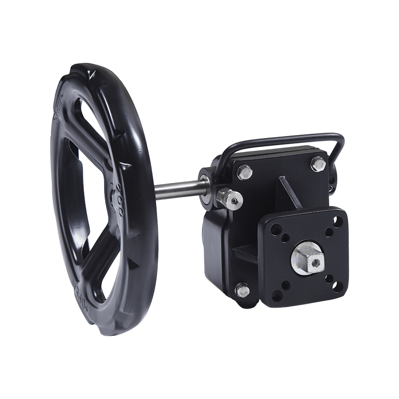 GD-Series Aluminum Declutch Part-Turn GearboxOffers manual override for pneumatic-actuated butterfly, ball, and plug valves, with ISO 5211 mounting and torque up to 5500 N·m.View Product →
Accessories are not cosmetic. A limit switch provides remote position feedback; a position indicator gives local visual confirmation; a handwheel lock or padlock device supports lockout/tagout. Our part-turn gearbox range covers manual and declutch configurations, and the accessory mounting follows the same ISO 5211 logic.
Mounting, accessories, and the checks that prevent callbacks
Most field problems with geared valves start at the mounting interface. Run these checks before commissioning:
- Confirm ISO 5211 flange size, stem dimensions, and bolt pattern against the valve datasheet.
- Check stem engagement depth: enough to transmit torque, not so deep that it bottoms out.
- Verify orientation keeps the handwheel accessible and the position indicator visible.
- Set the limit switch at the actual open and closed positions, not at the gearbox travel stops.
- Match lubricant and IP rating to washdown, outdoor, or corrosive service.
- Re-torque mounting bolts after the first thermal cycle or 100 operating cycles.
Accessories deserve the same care. A limit switch set by guesswork will report the wrong position even if the valve is correct. A handwheel that is too small will push rim force above the ergonomic limit. A declutch gearbox that is not properly engaged will leave the valve in manual mode after an actuator test.
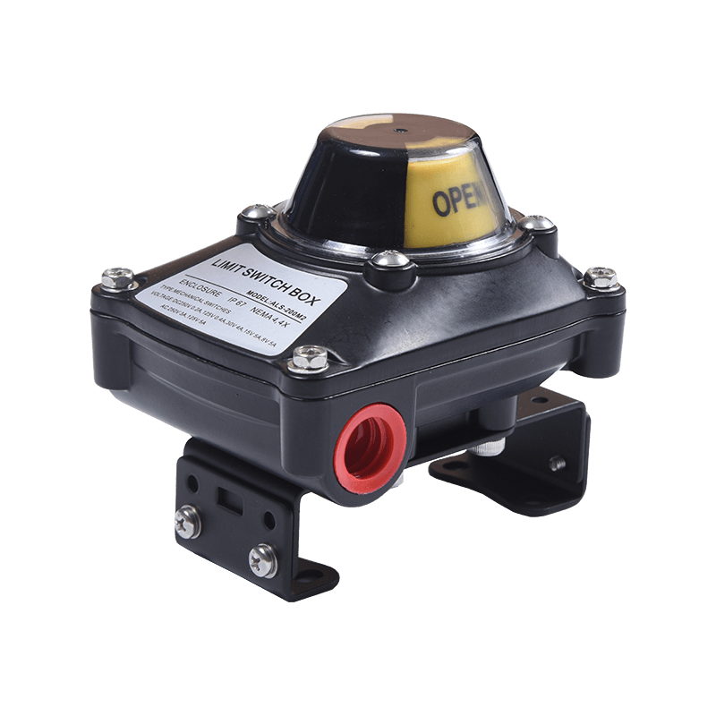 ALS-Series Valve Position Limit SwitchProvides hazardous-area-certified valve position feedback, dual cable entries, and adjustable ISO 5211 mounting for ALS-series installations.View Product →
Frequently asked questions about geared valves
What is a geared valve?
A geared valve is a quarter-turn valve fitted with a manual gear operator. The gearbox multiplies handwheel torque and usually self-locks, so the valve holds position without a brake.
When should I use a gear operator instead of a lever?
Use a gear operator when calculated operating torque exceeds comfortable lever effort, when the valve must stay put under vibration, or when the line size and pressure make a cheater bar unsafe.
Can I retrofit a gear operator to an existing valve?
Often yes, if the valve has an ISO 5211 mounting flange and a compatible stem. Check stem dimensions, engagement depth, and available handwheel clearance before ordering.
What does self-locking mean on a geared valve?
Self-locking means the worm gear cannot be back-driven by the valve. When the operator releases the handwheel, the disc or ball stays where it was set.
How do I know if the valve is open or closed?
Use the local position indicator and, for remote monitoring, a limit switch. Set the switch at the actual valve positions, not at the gearbox travel stops.
What maintenance does a valve gearbox need?
Inspect mounting bolts, keep the stem area clean, verify the limit switch setting, and follow the manufacturer's lubricant and IP rating guidance for the service environment.