

 en
 English
 Español

A DN150 cooling-water line is a common place to meet a butterfly valve that has started to weep at the flange, eight months in. The disc is unmarked, the stem turns freely, and yet the joint is wet.
In the field reports that reach a foundry's engineering desk, the cause is rarely the disc. It is almost always the seat compound sitting outside its temperature window, or an operator sized on line pressure instead of breakaway torque.
So the conclusion first: a butterfly valve is a quarter-turn valve whose real performance is decided by four specification choices — seat material, body and connection style, the stem-to-disc drive, and the operator mounted on the top pad. The disc itself is usually the least interesting part of the decision.
The mechanism is simple. A disc sits in the bore, carried on a stem that passes through the body wall. Ninety degrees of rotation takes it from edge-on to the flow to fully closed against a seat ring. Because the disc stays inside the flow path, the valve is short and light for its bore size, but it also means the seat and the disc edge live permanently in the medium.
Content
- 1 Inside a Butterfly Valve: Five Parts, One Weak Link
- 2 Torque Is Not a Flat Number Across the Stroke
- 3 Three Ways to Turn the Disc
- 4 Hand Levers: Fast, Cheap, and Limited by Rim Pull
- 5 Manual Gearboxes: When the Lever Stops Being an Option
- 6 Pneumatic Actuators: Speed, Remote Control, and a New Set of Checks
- 7 Seat, Body and Connection: The Table Buyers Argue Over
- 8 A Short Checklist Before the Purchase Order
- 9 Frequently Asked Questions
- 9.1 Q1. What is the difference between a butterfly valve and a gate valve?
- 9.2 Q2. Wafer or lug butterfly valve — which do I need?
- 9.3 Q3. How is butterfly valve torque calculated?
- 9.4 Q4. What temperature can an EPDM seat butterfly valve handle?
- 9.5 Q5. Why is my butterfly valve leaking?
- 9.6 Q6. Can a butterfly valve be used for throttling?
Inside a Butterfly Valve: Five Parts, One Weak Link
The body is a short cylinder clamped between two pipe flanges. Inside it sits the seat ring, and inside the seat sits the disc. A stem passes through the body wall, keyed or pinned to the disc, so that torque applied above becomes rotation below. On the top pad — usually machined to an ISO 5211 pattern so a lever, gearbox or actuator can be swapped without breaking the line — the operator turns your input into a quarter turn.
Five components carry the duty, and each fails in a characteristic way.
| Component | Job in the valve | Characteristic failure |
|---|---|---|
| Body | Carries the bore and clamps between flanges | Corrosion at the flange face; distortion when a wafer body is squeezed by uneven bolt torque |
| Disc | Blocks or passes the flow through 90° of rotation | Erosion of the trailing edge in slurry; nicked edge after closing on debris |
| Seat | Provides the sealing contact around the disc edge | Swelling, hardening or permanent set from the wrong medium or temperature |
| Stem | Transmits torque from the operator to the disc | Bending under an oversized actuator; galvanic corrosion where it meets the disc |
| Top pad and operator | Multiplies and applies the quarter turn | Under-sized actuator, or a lever nobody can safely reach |
Torque Is Not a Flat Number Across the Stroke
Two torque peaks matter, and neither of them sits in the middle of the stroke. The first arrives at unseating: the disc has been pressed into a resilient seat for weeks and the elastomer takes a set, so breaking that contact can demand more torque than anything else in the travel. The second arrives at seating, as the disc edge is forced into the seat and the last few degrees compress the rubber. Between roughly 20° and 70° the disc is edge-on, and the load is mostly bearing friction and fluid drag.
An operator sized on the running torque measured mid-stroke will stall exactly when the valve must not stall. The working number is breakaway torque at the worst differential pressure the line can produce, multiplied by a safety factor that most specifications place between 1.3 and 1.5. Get that figure wrong in either direction and the valve either fails to seat, or the stem and disc key absorb the overshoot. The step-by-step torque calculation for actuator sizing walks through the arithmetic.
Three Ways to Turn the Disc
Strip away the catalogues and there are only three ways to move a disc through 90°: a lever, a gearbox, or a pneumatic actuator. None of them wins on every axis, and the chart below is essentially the argument most buyers end up having with their own maintenance team.
The honest ranking: levers win on cost, speed and simplicity right up to the point where the torque requirement passes what an arm can deliver. Gearboxes win wherever the torque is real and the air supply is not. Actuators win when the valve has to move without a person standing beside it.
Hand Levers: Fast, Cheap, and Limited by Rim Pull
A lever is a torque multiplier with a fixed ratio — your hand at the end of the arm. Comfortable continuous pull is usually taken as 200–250 N, with roughly 350 N as the practical ceiling for a determined two-handed pull. On a 200 mm lever that caps the output somewhere between 40 and 70 N·m: enough for small bore, low pressure duties, not enough for a DN200 disc working against 10 bar.
Three details decide whether a lever fits: the stem interface (square drive or keyway size), the mounting pattern on the top pad, and whether the handle must lock in position. A lever that cannot be locked open is a maintenance hazard on a line that gets worked on regularly.
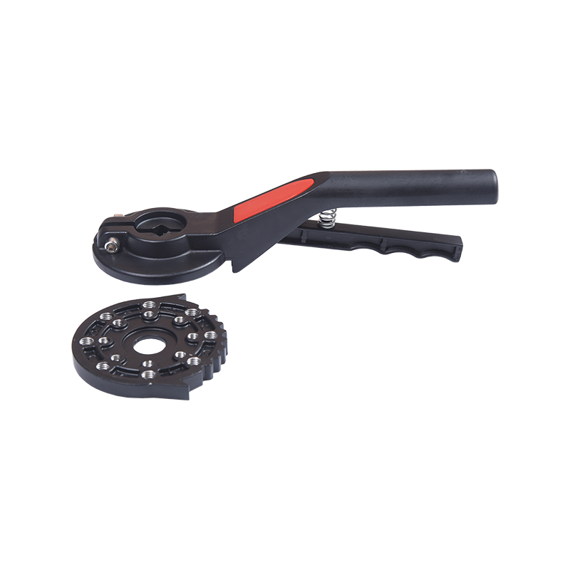 Butterfly Valve 30 Series Aluminum Hand LeverTwo lever models list square, flange, and torque ratings to match stem interface and mounting before selecting a quarter-turn valve operator.View Product →
Manual Gearboxes: When the Lever Stops Being an Option
A part-turn gearbox does one job: multiply a small handwheel input into a large quarter-turn output and then hold it. The ratio is chosen from the required output torque, and the trade-off is handwheel turns — a gearbox that needs thirty turns to cycle is not a valve anyone wants to work hourly.
Two families cover most of the duty. Manual gearboxes with an integral handwheel are the default for isolating service. Declutch types allow the same valve to run under an actuator in normal operation and by hand during an air failure, with the handwheel held disengaged until someone throws the lever. If the duty mixes both, the manual part-turn gearbox range is where the ratio, mounting pattern and handwheel orientation get fixed.
Pneumatic Actuators: Speed, Remote Control, and a New Set of Checks
Air is a cheap way to get repeatable quarter-turn motion, and it removes the operator from the hazardous side of a line. The choice between double-acting and spring-return is really a question about failure: a spring-return unit drives the disc to a defined position when supply pressure is lost, which matters on cooling water, fuel and anything that must fail closed.
What gets forgotten is everything around the actuator. Air quality determines seal life, so a filter-regulator belongs upstream. Position feedback needs a limit switch box on the actuator's accessory pad, wired before commissioning rather than after the first fault call. And the actuator's own travel stops must be set so the disc seats without being over-driven into the ring.
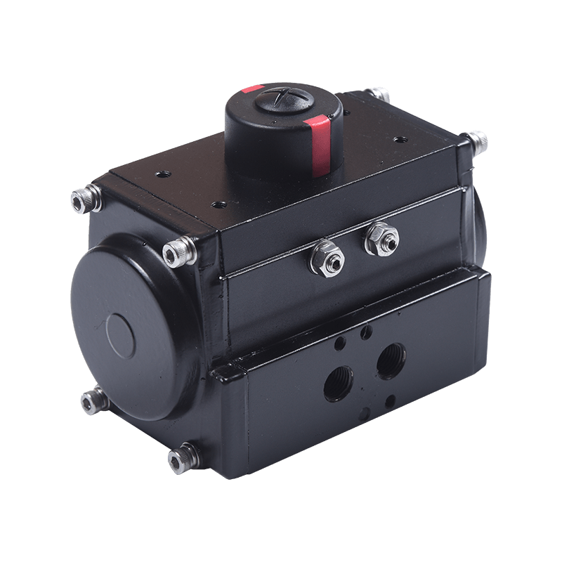 Hawks 10 Series Pneumatic Quarter-Turn ActuatorISO 5211 and NAMUR mounting support solenoid valves, limit switches, and positioners, with DA/SR models and torque tables for valve automation selection.View Product →
Seat, Body and Connection: The Table Buyers Argue Over
Seat compound is where most specifications are won or lost, because it is the one part that is always in contact with the medium. Body material follows the same logic: cast and ductile iron for water and wastewater, CF8 or CF8M stainless for corrosive service, aluminium where weight matters more than pressure class.
| Seat material | Practical temperature | Best suited to | Watch out for |
|---|---|---|---|
| EPDM | −40 to 120 °C | Water, wastewater, mild slurries | Oils, solvents and aromatic hydrocarbons |
| NBR | −10 to 80 °C | Oils, fuels, hydrocarbon service | Hot water, ozone and sunlight |
| PTFE / RPTFE | −20 to 200 °C | Acids, alkalis, hot water, CIP cycles | Abrasive slurry; cold flow at high pressure |
| Metal (SS316 / duplex) | Up to 400 °C and above | High temperature, abrasive media, fire-safe duty | Bubble-tight shut-off at low differential pressure |
Connection style is the other half of the argument. Wafer bodies are clamped by both flanges and cannot be pulled from a live line. Lug bodies have threaded inserts in their own ears, so each side bolts independently and the downstream pipe can be dropped for maintenance. Double-flanged bodies cost more again but suit large bore and high pressure where flange alignment is difficult.
A Short Checklist Before the Purchase Order
- Media, concentration and solids content, including what the line is flushed with during cleaning.
- Minimum and maximum temperature, not just the normal operating point.
- Differential pressure across the closed disc — this drives breakaway torque, not line pressure alone.
- Cycle frequency per day, which decides whether a lever is acceptable or an actuator is mandatory.
- Available rim pull or air supply pressure at the valve, measured rather than assumed.
- Design standard and top pad pattern, so the operator can be replaced without changing the valve.
- Spare seat availability, because the seat will be the first part replaced.
Frequently Asked Questions
Q1. What is the difference between a butterfly valve and a gate valve?
A gate valve slides a wedge clear of the bore, giving almost no pressure loss, but it is tall, slow and prone to sticking after long service. A butterfly valve rotates a disc in place, needs far less space and cycles quickly, at the cost of a pressure drop across the disc and a seat that sits permanently in the medium.
Q2. Wafer or lug butterfly valve — which do I need?
A wafer body is clamped between two flanges and cannot be removed from a live line. A lug body carries threaded inserts in its own ears, so each flange bolts independently and the downstream pipe can be disconnected for maintenance. Lug costs more and takes more bolts, but it is the practical choice for anything serviced in place.
Q3. How is butterfly valve torque calculated?
Breakaway torque combines seating interference, stem friction and hydrodynamic load at the worst differential pressure; seating torque is the load as the disc enters the seat. In practice engineers size on breakaway torque with a 1.3–1.5 safety factor, then check the result against the maker's published torque table for that bore and seat compound.
Q4. What temperature can an EPDM seat butterfly valve handle?
Roughly −40 °C to 120 °C in water and wastewater duty, with some compounds rated to about 150 °C for short excursions. Above that the elastomer hardens and takes a permanent set, so hot water, steam and CIP cycles generally move the specification to PTFE or a metal seat.
Q5. Why is my butterfly valve leaking?
In order of frequency: debris trapped between disc and seat, a seat compound swollen or hardened by the medium, uneven flange bolt torque distorting a wafer body, and an actuator stopping a few degrees short of the seat. Check travel first — it is the cheapest diagnosis and the most common cause.
Q6. Can a butterfly valve be used for throttling?
Yes, within limits. Between roughly 30° and 70° the disc sheds a wake that can vibrate the disc and stem, so long-term throttling in that band wears stem bearings. For continuous control duty, specify a valve rated for modulating service and keep the operating point out of the high-vibration band.