

 en
en
 English
 Español
A butterfly valve on a filter backwash line shows CLOSED on the control room screen, but media still slips past the seat. The disc is sitting about six degrees off the seat, and the signal that convinced the PLC the valve was shut came from a cam inside a limit switch box that was set by hand during commissioning. Nothing actually failed. The switch did exactly what it was told to do, and that is the problem.
A valve limit switch is a position sensor inside a housing. Treated that way at the drawing stage, it costs a few minutes of attention. Treated as an accessory bolted on at the end of a project, it becomes a recurring maintenance item and, in interlock duty, a real risk. Below: what the device does, where it mounts on part-turn valves, which datasheet numbers decide whether it works, and how to set cams so useful over-travel remains.
Content
- 1 What a Valve Limit Switch Actually Does
- 2 Where a Limit Switch Mounts on a Part-Turn Valve
- 3 The Datasheet Numbers That Decide the Outcome
- 4 Cam Setting, Over-Travel and Hysteresis
- 5 Failure Modes That Show Up in the Field
- 6 Sourcing Considerations for OEM and Project Buyers
- 7 Frequently Asked Questions
- 7.1 Q1. What is a valve limit switch used for?
- 7.2 Q2. What is the difference between a limit switch and a position transmitter?
- 7.3 Q3. What IP rating does a valve limit switch need?
- 7.4 Q4. Can a limit switch be fitted to a manual part-turn gearbox?
- 7.5 Q5. How do you set the cams on a valve limit switch?
- 7.6 Q6. What is the difference between SPDT and DPDT contact blocks?
What a Valve Limit Switch Actually Does
A limit switch converts mechanical valve position into a discrete electrical signal. Inside the housing, a shaft driven by the stem, gearbox or actuator carries adjustable cams. Each cam trips a contact block at a set angle, changing a normally open or normally closed circuit, and the control system reads that change as open, closed, or not in the expected position.
Two points prevent most specification errors:
- A limit switch is not a position transmitter. It reports discrete states at set angles; a 4-20 mA transmitter reports a continuous angle and costs considerably more. Most projects need one or the other, not both.
- The contact block rating decides survival, not the housing. Blocks are classified under IEC 60947-5-1 in utilisation categories such as AC-15 (AC control circuits) and DC-13 (DC control circuits). The DC-13 figure is usually a fraction of the AC-15 figure for the same block. Selecting on the AC number and then switching a 24 VDC solenoid coil is a reliable way to weld contacts shut.
Sensing options are fewer than a catalogue suggests: mechanical SPDT or DPDT blocks for general open/close indication and interlocks, inductive proximity sensors where cycle counts are high, and magnetic reed switches where contacts must stay sealed in wet environments.
Where a Limit Switch Mounts on a Part-Turn Valve
Three mounting routes appear in practice, and each changes what the switch is really measuring.
- On a manual part-turn gearbox. The switch sits on the gearbox top flange, driven by a shaft adaptor, so the gearbox output becomes the position reference for a hand-operated valve. How a part-turn gearbox works is useful background before fixing the adaptor geometry.
- On a pneumatic actuator. The box mounts on the actuator accessory interface. For part-turn actuators that interface follows VDI/VDE 3845, commonly called NAMUR, while the valve-to-actuator flange follows ISO 5211. A box built to both interfaces drops onto most quarter-turn actuators without a special adaptor drawing.
- Directly on the valve stem with a bracket. Used where no gearbox or actuator is present. The bracket then becomes the weak link: any flex under torque appears as position error.
Schematic of a switch box on a part-turn interface; internal cams and terminal block sit behind the cover.
Mounting accuracy matters more than buyers expect. Two degrees of lost motion in a shaft adaptor consumes roughly a fifth of the resolution available across a 90 degree travel range, before any cam adjustment begins.
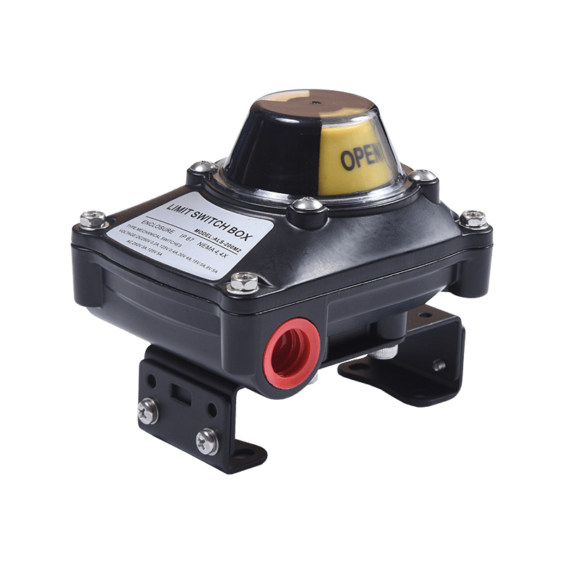 ALS series Limit Switch1. Compact and Beautiful Design, Polyester powder-coated aluminum die-casting housing or stainless steel (304/316) housing.、View Product →
Where the switch is bought as a catalogue item rather than a custom assembly, confirm shaft adaptor, cam configuration and cable entry against the actuator drawing at quotation stage.
The Datasheet Numbers That Decide the Outcome
Most valve limit switch failures trace back to a parameter that never made it into the purchase specification.
| Parameter | Typical options | Why it decides the result |
|---|---|---|
| Enclosure protection | IP65, IP66, IP67, IP68 to IEC 60529 | IP67 covers temporary immersion for 30 minutes at 1 m. Pits and washdown zones need it; a dry indoor skid does not. |
| Contact configuration | SPDT, DPDT, two independent SPDT | Separate indication and interlock signals need DPDT or a second block. |
| Contact rating | AC-15 and DC-13 values per IEC 60947-5-1 | The DC-13 rating is normally far lower than AC-15 on the same block. |
| Travel range and cam adjustment | 0-90 degrees adjustable, with fine trim | Covers butterfly, ball and plug valves; 120 degree duties need written confirmation. |
| Cable entry | M20 x 1.5, 1/2 in NPT | A gland that does not match the entry is a direct water path to the terminal block. |
| Housing material | Die-cast aluminium, powder coated | Handles impact, UV and washdown better than thin sheet metal. |
| Ambient temperature | Commonly -20 to +80 °C | Cold stiffens grease and seals; heat softens gaskets and shortens contact life. |
| Shaft adaptor | Square, star or keyed to match the driving shaft | A mismatched adaptor creates lost motion that no cam setting can remove. |
| Visual indicator | Dome or arrow with a 0-90 degree scale | Allows field verification without removing the cover. |
Cam Setting, Over-Travel and Hysteresis
On a 90 degree valve, the closed cam is normally set a few degrees before the disc reaches the seat, and the open cam a few degrees before the mechanical stop. Two numbers govern whether that works: over-travel available to the block after actuation, and hysteresis, the differential travel between actuation angle and reset angle.
Setting a cam two degrees from the stop with a block that has five degrees of hysteresis produces chatter: the contact resets, re-trips and floods the PLC with conflicting signals. A wider margin costs nothing in accuracy.
Design example on a 90 degree cycle; margins are calculated from the set angle, not measured field data.
Adjustment sequence that holds up: drive the valve to the closed position, loosen the cam screw, rotate the cam until the contact just trips, then lock the screw. Repeat at the open position. Cycle the valve several times and confirm the signal at the PLC input rather than with a continuity tester at the terminal block. Cam screws are mechanical fasteners and move under vibration, so serrated cam faces or a thread-locking compound are worth requesting.
Failure Modes That Show Up in the Field
Service reports for quarter-turn position feedback repeat six causes:
- Water ingress through a mismatched gland. Contacts corrode and signals turn intermittent months before they fail completely.
- Cam drift. Vibration and daily thermal cycling move a cam locked only by hand, so indication stops matching the valve.
- Welded contacts on DC inductive loads. Solenoid coils and relays on 24 VDC circuits produce a kick that a block rated only on its AC figure cannot absorb.
- Over-travel damage. A cam set too far from the stop lets the actuator push the block past its travel limit, bending the plunger or lever.
- Lost motion in the adaptor. The switch lags the valve by two to five degrees, so reported position is systematically wrong at both ends.
- Breathing housings. A sealed box that heats in the sun and cools at night draws humid air through a worn gasket.
The same list applies when a hand-operated valve is converted to automated duty. Moving the switch from a gearbox top flange to an actuator accessory interface also changes the torque picture: the actuator must be sized against valve break torque, not running torque.
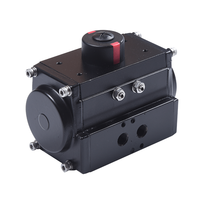 10 series Pneumatic ActuatorDesigning Features of Hawks 10 Series Pneumatic ActuatorView Product →
When automation is the plan, specify actuator, switch box and mounting interface together, so the accessory stack is dimensioned in one pass instead of three.
Sourcing Considerations for OEM and Project Buyers
Limit switches are simple enough that price differences are easy to see and quality differences are not. Five points separate a switch that lasts a decade from one replaced twice a year.
- Fix the interface first. Write ISO 5211 and VDI/VDE 3845 into the drawing before requesting quotations. Interface mismatches are the most expensive late change on a valve package.
- Look at the housing, not the label. A die-cast aluminium body with a proper powder coat resists impact and UV far better than stamped sheet metal.
- Ask for evidence. Enclosure ratings to IEC 60529, casting material certificates, terminal numbering and a wiring diagram should be available without negotiation.
- Confirm the wear parts. Cams, shaft adaptors, gaskets and indicator domes should be orderable as spares, ideally ex stock.
- Use the supplier's engineering time. Adaptor geometry, cam profiles, terminal layouts, nameplates and cable entries are all reasonable customisation points for OEM programmes, and a supplier that casts and machines in-house usually absorbs a drawing change without retooling the whole assembly. Our casting and machining capability is a fair place to start that conversation.
On manually operated valve packages the switch and the gearbox are usually bought together, and the fit between them decides how well indication tracks the valve.
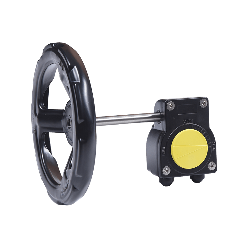 20-series Manual Aluminum Part-turn GearboxIntroduction and FeaturesView Product →
Frequently Asked Questions
Q1. What is a valve limit switch used for?
It converts valve position into discrete electrical signals, usually open and closed, for remote indication, PLC interlocks, pump sequencing and safety logic. Some builds add a mid-travel signal.
Q2. What is the difference between a limit switch and a position transmitter?
A limit switch gives on/off states at set angles. A position transmitter outputs a continuous 4-20 mA signal proportional to travel. Use a switch for indication and interlocks, a transmitter for modulating control.
Q3. What IP rating does a valve limit switch need?
Indoor skids are often fine with IP65. Outdoor, washdown and pit installations call for IP66 or IP67 to IEC 60529, where IP67 covers temporary immersion for 30 minutes at 1 m.
Q4. Can a limit switch be fitted to a manual part-turn gearbox?
Yes. Most manual part-turn gearboxes accept a switch box on the top flange with a shaft adaptor, so a hand-operated butterfly or ball valve can report position back to the control room.
Q5. How do you set the cams on a valve limit switch?
Drive the valve closed, rotate the closed cam until the contact trips, and lock the screw. Repeat at the open position, leaving a few degrees of over-travel, then cycle the valve several times to confirm repeatability.
Q6. What is the difference between SPDT and DPDT contact blocks?
SPDT gives one changeover circuit per switch; DPDT gives two independent changeover circuits, which lets indication and interlock signals come from the same cam without sharing a contact.