

 en
en
 English
 Español
A safety engineer at a wastewater treatment plant is called to investigate a failed emergency shutdown. The 12-inch butterfly valve on the main feed line was supposed to be fully closed, but the control room received no position signal because the valve position indicator had been removed during a retrofit and never reinstalled. The unit overflowed, a valve actuator was damaged, and the plant lost five hours of production.
That is why a valve position indicator is never an optional accessory on a critical-duty valve package. It converts an invisible mechanical state into a visible, control-room-ready signal. When the right indicator is installed, operators can trust the status readout. When it is missing or incorrect, the whole automation loop is blind.
Content
- 1 What Is a Valve Position Indicator?
- 2 How Does a Valve Position Indicator Work?
- 3 Types of Valve Position Indicators
- 4 How to Select the Right Valve Position Indicator
- 5 Common Applications in Industrial Fluid Control
- 6 Integration with Valve Actuation Systems
- 7 Maintenance and Troubleshooting
- 8 Valve Position Indicator FAQ
- 8.1 Q1: What is a valve position indicator?
- 8.2 Q2: What is a limit switch box?
- 8.3 Q3: How does a valve position indicator work?
- 8.4 Q4: How to choose a valve position indicator?
- 8.5 Q5: What are the common types of valve position indicators?
- 8.6 Q6: What is the difference between a valve position indicator and a valve positioner?
What Is a Valve Position Indicator?
A valve position indicator is a mechanical-electrical device that detects the physical position of a valve stem and converts it into visual or electrical feedback. In most industrial sites, this equipment is used on on-off isolation valves, where the essential question is simply: is the valve fully open or fully closed?
The same device is known by several interchangeable names: limit switch box, position switch box, valve position feedback assembly, or simply position indicator. However, a valve positioner is a different product. A positioner modulates air pressure to an actuator to maintain a target valve setpoint, while a position indicator only reports where the valve actually is.
How Does a Valve Position Indicator Work?
The operating sequence of a typical electromechanical position indicator is simple:
- The valve stem rotates as the actuator or gearbox turns.
- A cam assembly inside the indicator housing follows the stem rotation.
- The cam presses or releases microswitches or proximity sensors.
- The switch contacts close or open the signal circuit.
- The control system reads the signal and displays the valve status.
- A visual flag or colored disc in the housing turns to provide local confirmation.
Depending on the actuator configuration, the device may be mounted directly on the actuator drive shaft or indirectly on a transfer case. This mechanical-to-electrical signal conversion is the core value of a valve position indicator.
Types of Valve Position Indicators
Field conditions and safety requirements decide which type of position indicator should be used.
| Type | Signal Output | Typical Housing | Best Use |
|---|---|---|---|
| Mechanical / visual | Visual flag, scale | Aluminum or plastic | Manual valves, local indication |
| Electromechanical limit switch box | ON/OFF dry contacts | Aluminum, stainless steel or cast iron | Automated on-off valves, PLC/DCS |
| NAMUR sensor type | NAMUR signal | Ex-proof stainless steel | ATEX/IECEx hazardous areas |
| Analog / smart transmitter | 4-20mA / HART | Stainless steel | Proportional valves, PID control |
| Wireless indicator | Radio signal | Stainless steel, solar option | Remote or hard-to-wire sites |
The electromechanical limit switch box is the most widely used type. It is simple, durable, and easy to replace in the field, which is why it appears on most automated and manual valve packages in standard process plants.
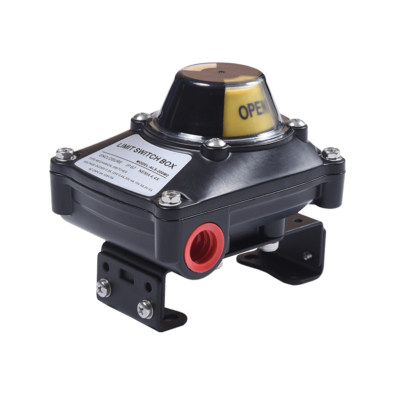 ALS Series Limit Switch Box for Reliable Valve Position FeedbackThe ALS series limit switch box features a compact, corrosion-resistant housing with IP67 protection and hazardous area certifications. It pairs with manual, pneumatic, or declutching gearboxes to provide accurate open/closed signals to control systems.View Product →
This type of switch box is often paired with manual gearboxes, pneumatic actuators, or declutching gearboxes to provide open/closed feedback to a PLC or DCS.
How to Select the Right Valve Position Indicator
When an OEM engineer specifies a position indicator for a valve package, the six criteria below are the practical decision points.
- Rotation angle. Quarter-turn valves need a 90-degree indicator; multi-turn valves require a continuous or stepped output.
- Signal type. Select dry contacts for simple on-off logic, NAMUR sensors for intrinsically safe circuits, or 4-20mA/HART for proportional feedback.
- Enclosure protection. Match IP67/IP68 for wet environments and Ex d or Ex ia for hazardous areas.
- Interface dimensions. The indicator input bore must match the actuator output shaft, whether it is ISO 5211 mounting or a specific stem size.
- Environmental conditions. Stainless steel housings are preferred for aggressive chemicals, offshore and coastal sites.
- Switch reliability. Confirm contact rating, mechanical cycle life, and operating temperature range.
The radar chart below compares three indicator families on five key properties.
Common Applications in Industrial Fluid Control
The majority of valve position indicators are used in five industrial sectors: oil and gas, water and wastewater, power generation, chemical processing, and food and beverage. The exact mix varies by region, but the pattern is consistent. Wherever a valve must be monitored remotely or closed automatically for safety, a position indicator is part of the package.
Automated on-off valves in the oil and gas sector usually combine a pneumatic actuator with a limit switch box to provide remote open/closed status. A compact, double-acting actuator is a typical example of a quarter-turn automated valve package.
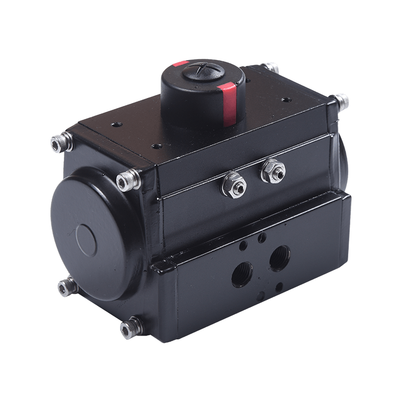 10 Series Pneumatic Actuator for Quarter-Turn Valve AutomationThe 10 series pneumatic actuator offers a durable aluminum body, dual piston rack-and-pinion design, and modular spring cartridge for efficient, high-cycle operation. It supports ISO 5211 and Namur standards, making it ideal for automated on-off valve packages.View Product →
Integration with Valve Actuation Systems
A position indicator is only as valuable as the package it is mounted on. With a manual part-turn gearbox, the indicator is installed directly on the gearbox drive shaft and gives the operator a local visual status. On a pneumatic actuator, the switch box is mounted on the actuator top hatch and provides the open/closed signal that the automation system needs. On a declutchable gearbox, the indicator continues to work whether the valve is operated manually or through an automatic drive.
This combination is common in modern plants. A declutching gear allows an operator to switch between handwheel operation and automatic actuation without losing position feedback.
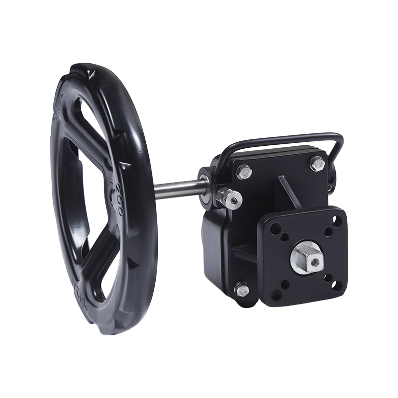 GD-Series Aluminum Declutch Part-Turn Gearbox for Manual OverrideThe GD-series declutch gearbox enables manual operation of automated valves during installation or air failure. Its lightweight design mounts directly to pneumatic actuators without a distance plate, offering smooth switching and IP65 weatherproofing.View Product →
At our vertically integrated manufacturing facility, the casting, machining, and assembly steps are kept in-house. That helps OEM customers match the actuator, gearbox, and position indicator to the exact torque and feedback requirements of the valve. Learn more about our manufacturing approach.
Maintenance and Troubleshooting
A reliable limit switch box still needs periodic attention after installation and commissioning.
- Signal loss or intermittent feedback: check terminal torque, cable damage, and microswitch contacts.
- Cam drift after long service: re-tighten the cam screws and perform a full calibration.
- Water ingress: inspect the O-rings and cable glands, then replace worn seals.
- Visual indicator jamming: clean the sight glass and confirm the color disc rotates freely.
- Corrosion in aggressive environments: upgrade to a stainless steel housing or a NAMUR sensor type.
These checks are usually scheduled during valve maintenance or after any actuator work.
Valve Position Indicator FAQ
Q1: What is a valve position indicator?
A valve position indicator is a device that converts the mechanical position of a valve into a visual or electrical signal for operators and control systems.
Q2: What is a limit switch box?
A limit switch box is another common name for a valve position indicator. It mounts on the actuator and uses microswitches to send open/closed feedback.
Q3: How does a valve position indicator work?
A cam on the indicator shaft follows the valve stem rotation, actuates a switch, and sends a signal to the control room or a local junction box.
Q4: How to choose a valve position indicator?
Match the rotation angle, signal type, enclosure rating, interface dimensions, and environmental conditions to the actuator and the process area.
Q5: What are the common types of valve position indicators?
Mechanical/visual indicators, electromechanical limit switch boxes, NAMUR sensors, analog smart transmitters, and wireless indicators.
Q6: What is the difference between a valve position indicator and a valve positioner?
A position indicator is a feedback device that reports valve state. A positioner adjusts actuator pressure to maintain a target valve position.