

 en
en
 English
 Español
Two documents arrive with the same quarter-turn valve package: a pneumatic schematic diagram and a pneumatic actuator datasheet. The drawing shows a 5/2 solenoid valve feeding a double-acting rotary actuator, with a spring drawn in the end box for fail-close duty. The datasheet quotes an output torque at 5.5 bar. Neither document answers the question that decides whether the line really isolates: will that actuator seat the disc at 4 bar on a cold morning, with a spring eating part of the output?
A pneumatic schematic diagram is a logic document. It fixes positions, port connections, flow paths, sequence and fail direction, and it is normally drawn in the de-energized state using symbols defined by ISO 1219-1 and laid out under ISO 1219-2. It does not size anything. Force, torque, air consumption and mounting interfaces are engineering values that sit behind the symbols, and that gap is where most part-turn problems begin.
Content
- 1 What the drawing defines and what it leaves blank
- 2 Valve symbols: positions, ports and the flow box
- 3 The actuator side: cylinders, rotary actuators and fail position
- 4 Two numbers the drawing never shows: force and air consumption
- 5 From the drawing to a mounted part-turn assembly
- 6 Feedback and manual override: the symbols people forget
- 7 Gear reducers: the block between actuator and valve
- 8 Standards and the purchasing risks behind tidy symbols
- 9 Frequently asked questions about pneumatic schematic diagrams
- 9.1 Q1. What is a pneumatic schematic diagram?
- 9.2 Q2. What do the numbers 1, 2, 3, 4 and 5 mean on a pneumatic valve symbol?
- 9.3 Q3. How can I tell if a 5/2 valve is spring return or double solenoid?
- 9.4 Q4. Can I size a pneumatic actuator from a schematic diagram?
- 9.5 Q5. What is the difference between a 4/2 and a 5/2 pneumatic valve?
- 9.6 Q6. Do I need a gearbox with a pneumatic actuator on a butterfly valve?
What the drawing defines and what it leaves blank
Read a schematic the way you read a wiring diagram: it shows what connects to what, and in which order, not how large the conductor has to be.
A well-drawn pneumatic schematic diagram will tell you:
- the valve type and its position count, such as 3/2, 5/2 or 5/3;
- the route of compressed air from the supply through to the exhaust;
- how each valve is actuated, whether by manual lever, pilot pressure, solenoid or spring;
- the fail position when air or electrical power is lost;
- which accessories sit in the circuit, such as filter-regulators, silencers, limit switches and manual overrides.
It will not tell you:
- cylinder bore, stroke or rotary actuator torque;
- valve flow coefficient and the pressure drop across the circuit;
- materials, port threads and dimensional tolerances;
- the mounting interface between actuator, gearbox and valve.
The last point has commercial consequences. Two suppliers can draw an identical 5/2 circuit and still ship parts that will not bolt together, because the drawing says nothing about flange size or spool interface.
Valve symbols: positions, ports and the flow box
The square is a position, not a component
Each square in a directional control valve symbol represents one valve position, so two squares mean two positions. Inside a square, an arrow marks a flow path that is open in that position, while a perpendicular line or a T marks a blocked port. The box drawn nearest the port connections is the position the valve takes when it is not actuated, which is how fail position is read straight off the drawing.
Port numbers worth memorizing
- Port 1: pressure supply from the air preparation unit.
- Ports 2 and 4: working lines running to the actuator.
- Ports 3 and 5: exhaust ports, usually fitted with silencers or speed controllers.
- Ports 12 and 14: pilot signal lines for pilot-operated valves.
Ways versus ports
A 5/2 valve has five ports and two positions; a 3/2 valve has three ports and two positions. The practical difference between a 4/2 and a 5/2 valve is the exhaust path. The 5/2 valve gives each working line its own exhaust, which is why it dominates double-acting actuator circuits where each direction needs independent speed control.
The actuator side: cylinders, rotary actuators and fail position
Linear cylinders appear as a rectangle with a piston and a rod. Single-acting versions carry one air connection, double-acting versions two. Quarter-turn applications instead use a rotary or part-turn pneumatic actuator, drawn as a body with a rotating element and normally two air connections. Because a rotary actuator produces torque directly rather than through a linkage, its symbol tells you almost nothing about whether it can actually move the valve.
Spring return is drawn as a spring in the end box, and it is never free. A spring-return actuator gives up part of its air-driven output to compress the spring, so usable torque in the working direction is lower than that of an equally sized double-acting unit. When the schematic shows a spring and the valve datasheet quotes a seating torque, those two details have to be checked against each other rather than accepted separately.
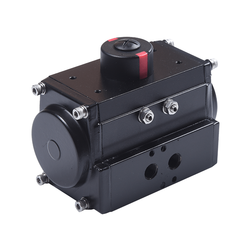 10 series Pneumatic ActuatorDesigning Features of Hawks 10 Series Pneumatic ActuatorView Product →
Two numbers the drawing never shows: force and air consumption
Force first. The theoretical push force of a cylinder is supply pressure multiplied by the effective piston area. At 6 bar on the piston side, standard bores translate into roughly the following values.
That figure excludes friction, spring force and pressure drop through tubing and fittings, and retract force is lower because the rod removes area from the piston. Rotary actuators behave in the same proportional way: available torque scales with supply pressure and vane or piston area, so dropping from 6 bar to 4 bar removes roughly a third of the output. This is why calculating the required torque for a pneumatic actuator is a separate exercise from reading the symbol.
Air consumption is the second invisible number. Every cycle that exhausts to atmosphere discards the compressed air held in the chamber, and for the same stroke, consumption rises with the square of the bore.
A 63 mm bore therefore consumes roughly four times the air of a 32 mm bore for the same stroke. That difference feeds into compressor sizing, cycle repeatability and valve flow coefficient. An undersized valve on a large bore produces slow, jerky motion even when the schematic itself is flawless.
From the drawing to a mounted part-turn assembly
Reading a pneumatic schematic diagram becomes useful only when it maps onto hardware. A quarter-turn assembly typically stacks its elements on one axis, and each symbol on the drawing corresponds to a physical block in that stack.
Air enters at port 1, the directional valve switches between ports 2 and 4, and the actuator converts that flow into torque. Where a gearbox is present, it multiplies the torque, and the limit switch reports the final position back to the control system.
Feedback and manual override: the symbols people forget
Limit switches usually appear as a small box connected to the actuator, driven by cams on the actuator shaft. They are the difference between a control system that knows the valve position and one that merely assumes it. When a schematic carries no position feedback, fail-safe logic has to rely on time delays instead, which is a familiar source of nuisance alarms and false trips.
Manual override shows up either as a handwheel on a gearbox or as a lever or screw on the solenoid pilot. It is easy to overlook on a drawing and the first thing an operator reaches for during a power failure.
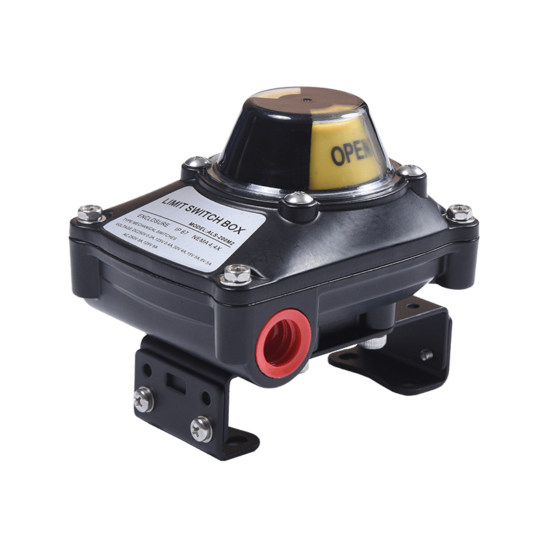 ALS series Limit Switch1. Compact and Beautiful Design, Polyester powder-coated aluminum die-casting housing or stainless steel (304/316) housing.、View Product →
Gear reducers: the block between actuator and valve
Some quarter-turn valves demand more torque than a compact actuator can deliver at the site's available air pressure. The conventional answer is a part-turn gearbox mounted between the actuator and the valve stem. It multiplies torque, adds a handwheel for emergency operation, and can include a declutch mechanism that switches between manual and automatic drive.
On the drawing, the gearbox is a small block with a handwheel symbol, sometimes with a clutch symbol beside it. Off the drawing it is a mechanical component with hard constraints: torque rating, ratio, mounting flange dimensions and stem acceptance. A valve gear reducer is chosen on those numbers, never on the symbol, which is why the full range of part-turn gearboxes is specified by interface and output rather than by picture.
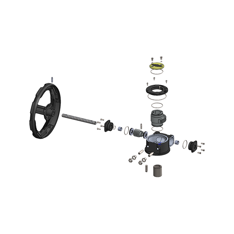 CF Series Valve Gear ReducersIntroduction to the CF Series Valve Gear ReducersView Product →
Standards and the purchasing risks behind tidy symbols
Symbols follow one standard; hardware follows several. That split is where procurement mistakes originate, because a correct schematic can still describe a stack that does not assemble.
| Symbol group | How it is drawn | What it fixes in the design |
|---|---|---|
| Directional control valves | Squares with arrows or blocked ports | Sequence, position count and fail position |
| Linear actuators | Rectangle with piston and rod | Motion type; bore and stroke still require sizing |
| Rotary and part-turn actuators | Body with rotating element and two air ports | Torque output; spring return reduces usable torque |
| Gearboxes and manual override | Handwheel or lever symbol beside a block | Torque multiplication and emergency operation |
| Accessories | Small boxes for filters, regulators, silencers and switches | Air quality, exhaust control and position feedback |
Three interface standards resolve most disputes before they reach the assembly bench: ISO 5211 for valve mounting flanges, ISO 5599 for valve interfaces, and VDI/VDE 3845 for actuator accessory mounting. Port threads are a fourth trap, since G and NPT threads look similar on a symbol and never interchange in the field. Asking for the interface drawing alongside the schematic removes far more risk than any further study of the symbols themselves.
Frequently asked questions about pneumatic schematic diagrams
Q1. What is a pneumatic schematic diagram?
It is a functional drawing showing how compressed air components are connected and sequenced, using ISO 1219-1 symbols in the de-energized state. It defines flow logic rather than component size.
Q2. What do the numbers 1, 2, 3, 4 and 5 mean on a pneumatic valve symbol?
Port 1 is the pressure supply, ports 2 and 4 are the working lines to the actuator, ports 3 and 5 are exhausts, and ports 12 and 14 are pilot signal lines.
Q3. How can I tell if a 5/2 valve is spring return or double solenoid?
Look at the end boxes. A spring symbol on one side means spring return with a defined fail position; solenoids on both sides mean the valve holds its last position when power is lost.
Q4. Can I size a pneumatic actuator from a schematic diagram?
No. The drawing gives function only. Sizing needs valve torque, supply pressure, a safety factor and the mounting standard, and it is calculated separately.
Q5. What is the difference between a 4/2 and a 5/2 pneumatic valve?
A 5/2 valve has separate exhaust ports for each working line, so each direction can be speed-controlled independently, while a 4/2 valve shares one common exhaust.
Q6. Do I need a gearbox with a pneumatic actuator on a butterfly valve?
Only when the required torque exceeds what a compact actuator produces at the site's air pressure, or when a manual handwheel is needed for emergency operation.
A pneumatic schematic diagram is the fastest way to understand what a circuit is meant to do, and the worst way to decide what to buy. Read it for sequence, ports and fail direction. Decide bore, torque, gearbox ratio and mounting interface from sizing calculations and interface standards. When the drawing and the datasheet disagree, the drawing usually wins on logic and the datasheet on capability, and it is capability that keeps a butterfly valve sealing on a cold Monday morning.