

 en
 English
 Español

A bench test at 7 bar makes almost any actuator look decisive. Move the same unit to a plant where the header sags to 4 bar during the morning shift, and a butterfly valve that should swing 90 degrees stops at 84. Nothing has failed. The supply simply fell below the pressure the torque calculation quietly assumed, and that gap between test-bench air and plant air is where most commissioning arguments begin.
The practical answer: run general-purpose pneumatic valve actuators between 2 and 8 bar, roughly 29 to 116 psi, and treat 5.5 bar (about 80 psi) as a reference point rather than a target. Double-acting units will normally stroke somewhere inside that window. Spring-return units need the upper half to compress the spring pack and only the lower edge to begin moving. Below the minimum the stroke stays incomplete; above the maximum, seal life shortens and the end stops absorb impacts they were never sized for.
Content
- 1 Where the 2–8 bar window actually comes from
- 2 Your real minimum is set by the valve, not the actuator
- 3 Spring-return actuators carry two pressure figures
- 4 What happens at each end of the range
- 5 Air quality, tubing and regulator droop are part of the pressure spec
- 6 Matching supply pressure to a real valve in four steps
- 7 When supply pressure drops, plan the manual override
- 8 Common questions about pneumatic operating pressure
- 8.1 Q1. What pressure range should a pneumatic actuator be operated at?
- 8.2 Q2. What is the minimum air pressure for a spring-return actuator?
- 8.3 Q3. Does higher air pressure increase actuator torque?
- 8.4 Q4. Why does my actuator stop short of a full 90 degree stroke?
- 8.5 Q5. Can I run a pneumatic actuator above 8 bar?
- 8.6 Q6. What air quality do pneumatic actuators need?
Where the 2–8 bar window actually comes from
Rack-and-pinion and scotch-yoke actuators turn air pressure into piston force, then turn that force into torque through the pinion radius. Output torque therefore tracks gauge pressure almost linearly. At 4 bar you see roughly 70 percent of the torque published at 5.5 bar; at 7 bar, roughly 125 percent. That straight-line relationship is exactly why one figure, 5.5 bar, became the common rating point for catalogue torque tables across the industry.
Bars show the usual working span. The nominal point behind most published torque figures is 5.5 bar.
Body ratings are a separate number and often misunderstood. Most general-purpose aluminium bodies are proof-tested well above the working range, but continuous service is usually capped at 8 bar. The test pressure proves the housing will not burst; the rated pressure tells you what the seals, bearings and end stops will tolerate shift after shift, year after year.
Your real minimum is set by the valve, not the actuator
An actuator datasheet tells you what torque it produces at a given pressure. It cannot tell you what your valve needs. Break-to-open torque, running torque and reseat torque are three different values, and the largest of them governs the selection. Common engineering practice applies a safety factor of 1.3 to 1.5 on top of the measured valve torque to cover temperature drift, dry seats and ageing seals.
| Supply pressure | Relative torque | What it means on site |
|---|---|---|
| 2 bar (29 psi) | about 36% | Marginal. Only workable for low-torque valves with a generous safety factor. |
| 3 bar (44 psi) | about 55% | Typical floor for a spring-return unit reaching full stroke. |
| 4 bar (58 psi) | about 73% | Common in older plants. Check the margin before approving the line. |
| 5.5 bar (80 psi) | 100% | The published rating point. Use it as the comparison baseline. |
| 7 bar (102 psi) | about 127% | Healthy margin. Watch end-stop loading on fast-stroking valves. |
| 8 bar (116 psi) | about 145% | Upper limit for most general-purpose units. |
If the arithmetic is unfamiliar, it is worth spending twenty minutes on the torque calculation behind actuator sizing before the valves arrive on site, because resizing afterwards is expensive.
Spring-return actuators carry two pressure figures
A double-acting unit has one minimum: whatever pressure produces the required torque. A spring-return unit has two, and mixing them up is one of the most common specification errors. The first is the pressure at which the spring pack just starts to move, often around 2 bar. The second, and the one that belongs on the datasheet you hand to a client, is the pressure needed to complete the full stroke against the spring with the rated load attached.
Because the springs consume torque throughout the travel, the spring-return variants in our 10 series pneumatic actuator range are specified with both figures separately rather than a single "operating pressure" line. When the supply hovers between the two numbers, the actuator will move but may not finish the stroke, and that is exactly the behaviour operators describe as a valve that "half closes".
What happens at each end of the range
- Below 2 bar: the piston force no longer overcomes seat friction plus spring load. Strokes shorten, position feedback drifts, and the solenoid may chatter as pilot pressure collapses.
- Between 2 and 3 bar: double-acting units often still work, spring-return units frequently do not. This is the ambiguity band where a valve can pass a bench check and fail in service.
- 5.5 to 6 bar: the normal operating sweet spot. Adequate torque margin with modest seal and impact loads.
- Above 8 bar: seal extrusion, accelerated lip wear and hard end-stop impacts. Faster stroking also raises water-hammer risk on liquid lines.
- Above 10 bar: outside the rating of most general-purpose aluminium bodies regardless of what a proof test suggests.
Air quality, tubing and regulator droop are part of the pressure spec
The gauge on the compressor is not the pressure the actuator sees. Every metre of tube, every elbow, every filter element and every solenoid valve removes a little of it, and a regulator sags below its set point exactly when a second actuator strokes and demand spikes. ISO 8573-1 gives the vocabulary for the air itself: particulate, water and oil classes. A practical industrial target is filtration around 40 micrometres, a dew point low enough to prevent condensate in the cylinder, and a small amount of oil mist only if the seals were designed for it.
Two habits close most of that gap. First, fit the regulator as close to the valve as practical and size tube by bore rather than by what is already in the store. Second, take the commissioning reading from a gauge at the actuator inlet while the valve is actually stroking, not at the filter while the line is idle. A 1 bar discrepancy between those two points is entirely ordinary.
Matching supply pressure to a real valve in four steps
- Collect the valve torque figures: break-to-open, running and reseat, at the actual line temperature.
- Apply a safety factor of 1.3 to 1.5 to the highest value.
- Read the actuator torque table at your lowest expected header pressure, not at the nominal 5.5 bar, and confirm the margin is positive.
- Check the upper limit, the air quality class and the accessory stack, then confirm the full-stroke pressure in writing for the spring-return case.
That third step is the one that saves projects. An actuator chosen on nominal torque and operated on a weak header is a valve that works in spring and jams in August, when demand is highest and pressure is lowest.
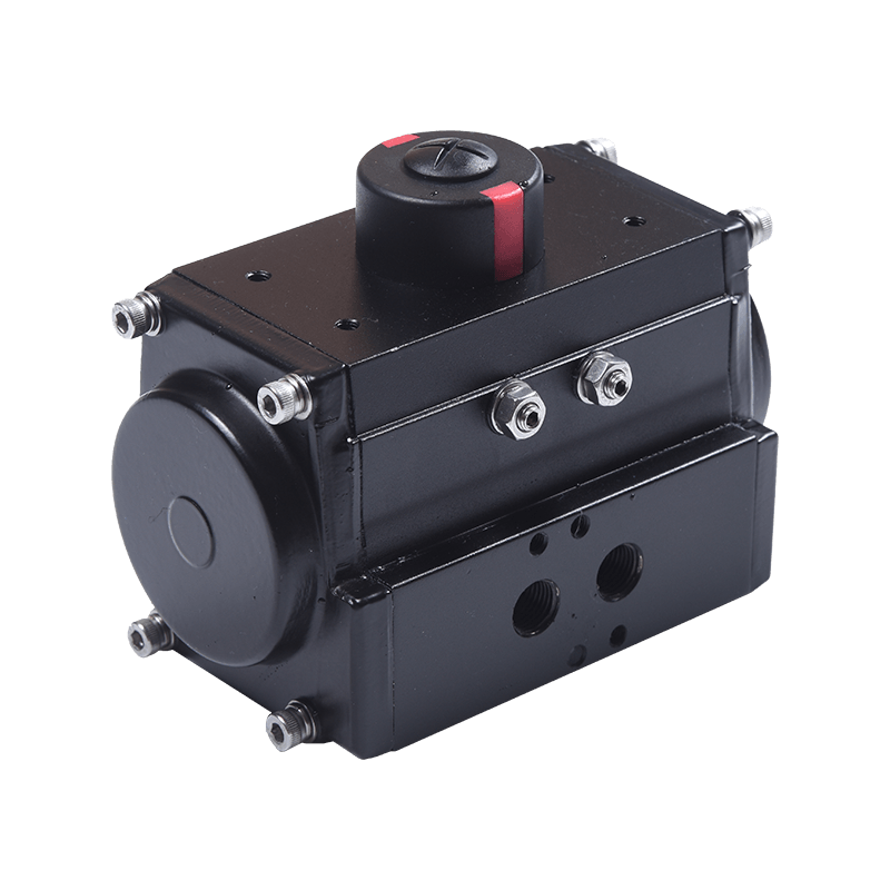 Hawks 10 Series Pneumatic Quarter-Turn Valve ActuatorRack-and-pinion actuator with double-acting and spring-return models, ISO/NAMUR mounting, and torque tables for sizing against real supply pressure.View Product →
When supply pressure drops, plan the manual override
No air system is perfectly reliable. If a line can fall below the full-stroke minimum during peak demand or a compressor trip, the operating procedure needs an answer, and "wait for pressure" is rarely one on a critical isolation valve. A declutchable gearbox sits between the actuator and the valve stem and lets a technician throw a lever, disengage the drive and finish the stroke by handwheel.
Sizing follows the same logic as the actuator: the handwheel must deliver the required valve torque at a realistic rim effort, so the gearbox ratio needs to be checked against the same 1.3 to 1.5 margin rather than chosen by flange size alone.
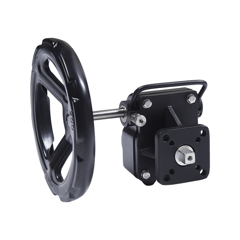 GD-Series Aluminum Declutch Part-Turn Gearbox for Manual Valve OperationCompact ISO 5211 declutch gearbox for butterfly, ball and plug valves, offering 180–5500 N·m torque and manual operation when air supply is unavailable.View Product →
Common questions about pneumatic operating pressure
Q1. What pressure range should a pneumatic actuator be operated at?
Most general-purpose valve actuators are designed for 2 to 8 bar, with 5.5 bar as the nominal point used in published torque tables.
Q2. What is the minimum air pressure for a spring-return actuator?
Movement may start near 2 bar, but full stroke against the spring usually needs 3 bar or more at the actuator inlet.
Q3. Does higher air pressure increase actuator torque?
Yes, almost linearly. Raising supply from 5.5 to 7 bar adds roughly a quarter more torque, but also more seal and end-stop load.
Q4. Why does my actuator stop short of a full 90 degree stroke?
Usually the inlet pressure is lower than assumed, or the valve torque exceeds the actuator output at that pressure. Check the gauge while stroking.
Q5. Can I run a pneumatic actuator above 8 bar?
Not continuously on a standard aluminium body. Higher proof pressure is a burst-safety check, not a working rating.
Q6. What air quality do pneumatic actuators need?
Filtered, dry air in line with ISO 8573-1 classes: around 40 micron filtration and a dew point low enough to stop condensate forming in the cylinder.