

 en
 English
 Español

A maintenance technician isolating a 4-inch cooling header has to spin a gate valve handwheel somewhere between 15 and 20 times before the flow stops. On the parallel line, the ball valve closes in a quarter turn — roughly two seconds, with one gloved hand. Both valves carry a PN16 rating. Both bolt to the same flange pattern. The difference is not build quality; it is kinematics.
That single mechanical fact drives everything downstream: how the valve is actuated, how much headroom it needs, how it fails, and what it costs to keep working. Below is how the two compare on the points that actually decide a specification.
Short answer: specify a gate valve when the line is normally open or normally closed and you want low cost per inch of bore, negligible pressure loss and a straight-through path for dirty media. Specify a ball valve when the line is isolated often, when the valve must be automated, when tight shut-off matters, or when there is no room for a rising stem. Neither is a throttling valve.
Content
How each valve actually closes
A gate valve converts rotary input into linear travel. The stem threads pull a wedge or a parallel disc up out of the flow path, and the final turns wedge the disc against two seat faces to shut the line. With the disc fully withdrawn, the bore behaves like a length of straight pipe — pressure drop is close to that of a spool piece, and a scraper or pig can pass through a pipeline gate valve without obstruction.
A ball valve does the opposite. A sphere with a cylindrical bore sits preloaded between two seats; a 90-degree rotation either aligns the bore with the pipe or turns the solid side of the sphere against the seats. There is no mechanically stable intermediate position, which is exactly why it is excellent at on/off duty and unsuitable for regulation.
Specification comparison at a glance
| Criterion | Gate valve | Ball valve |
|---|---|---|
| Operating motion | Multi-turn linear, typically 10–30 turns | Quarter turn, 90 degrees |
| Shut-off tightness | Metal-seated designs are rarely bubble-tight; resilient seats improve it | Soft-seated designs are typically bubble-tight in both directions |
| Pressure drop, full open | Essentially zero, straight-through bore | Essentially zero with a full port; reduced-port bodies restrict flow |
| Throttling | Not recommended — disc and seats erode | Short-term only; V-port balls help but are not control valves |
| Dirty media | Handles suspended solids; seats can score if grit is trapped | Media can pack into the body cavity and raise torque |
| Temperature ceiling | Metal seats suit high-temperature service | PTFE-based soft seats typically top out near 200 °C |
| Installed envelope | Rising-stem versions need headroom above the valve | Compact; allow swing room for a lever handle |
| Actuation | Multi-turn actuator with thrust and stem-nut adaptation | Quarter-turn gearbox or pneumatic actuator on an ISO 5211 pad |
| Cost curve | Cheaper per inch of bore as size increases | Competitive at small sizes, climbs steeply at large bores |
| Typical duty | Main isolation, buried or large lines, shutdown isolation | Frequent isolation, equipment isolation, utility and instrument lines |
On flow capacity, the two are closer than most people expect. Published selection tables from valve manufacturers usually place a 2-inch full-port ball valve within roughly 10–20% of a same-size gate valve in flow coefficient when fully open. The real divergence shows up in sealing, speed and actuation cost, not in the fully open condition.
Where each design fails first
Ball valve failure modes
- Seat swelling or extrusion when the elastomer or PTFE grade is wrong for the chemical being handled.
- Cavity packing — scale and debris collect behind the ball until operating torque climbs and the valve eventually seizes.
- Stem seal wear, especially on valves cycled many times a day without routine maintenance.
- Erosion of the ball's sealing band if the valve is habitually left half open instead of fully seated.
Gate valve failure modes
- Stem thread damage when a stuck valve is forced with a cheater bar; the thread takes the load, not the wheel.
- Seat scoring from being used as a throttle, which is the most common misapplication in plant rooms.
- Bonnet gasket leaks after repeated thermal cycling on steam service.
- Disc chatter and vibration whenever the valve sits partly open.
The practical consequence is worth stating plainly: a ball valve usually fails in a way the operator can feel, as rising torque on the handle. A gate valve often fails silently and is only discovered on the day someone needs to isolate the line.
Actuation is where the choice really costs money
Gate valves and ball valves need different actuation hardware, and at plant scale that difference shows up in the storeroom rather than on the drawing.
Automating a gate valve means a multi-turn actuator. It must deliver torque to rotate the stem and thrust to seat the disc, and it needs a stem nut and thrust bearing matched to the valve's thread. Sizing is iterative, and the actuator is generally larger and more expensive than a quarter-turn unit of the same pressure class.
Automating a ball valve is a quarter-turn problem, and the hardware is standardised around it. A worm-type part-turn gearbox multiplies handwheel torque on larger bores; a pneumatic or electric quarter-turn actuator drives the stem directly through an ISO 5211 mounting pad. If you want the mechanics behind the reduction ratio, our note on how a part-turn gearbox works walks through it.
Standardising isolation on quarter-turn valves also simplifies spares. One gearbox family covers a band of bore sizes, one actuator frame covers a band of valves, and one limit switch design reports position for all of them. That is the quiet saving nobody puts in the capital request.
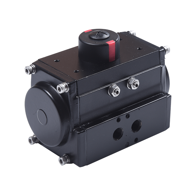 Hawks 10 Series Quarter-Turn Pneumatic ActuatorCompact rack-and-pinion actuator for standardized valve automation, with ISO5211/DIN3337 mounting, NAMUR accessory interfaces, and double-acting or spring-return variants.View Product →
Manual override deserves a line of its own. A declutch gearbox lets an operator disconnect the actuator and take over with a handwheel during a power or air failure — the difference between a controlled shutdown and a line that has to be drained.
Matching the valve to the duty
| Situation | Better fit | Why |
|---|---|---|
| Main isolation, 6 inch and above, operated rarely | Gate | Lower cost per inch of bore, negligible pressure loss |
| Isolated weekly for maintenance | Ball | Quarter turn, easy lockout, straightforward to actuate |
| Media above 200 °C | Metal-seated gate | Soft PTFE seats are the limiting component, not the body |
| Slurry or fibrous solids | Slurry-rated gate | Straight-through path with no cavity to pack |
| Remote on/off with position feedback | Ball | Quarter-turn actuator plus limit switch is the simplest loop |
| Flow or pressure regulation | Neither | Use a globe or control valve; both of these will be damaged |
For automated on/off duty, the actuator is only half the package. A position monitor is what tells the control room the valve actually moved, and a mechanical switch box that trips on the stem position is still the most common answer in harsh environments.
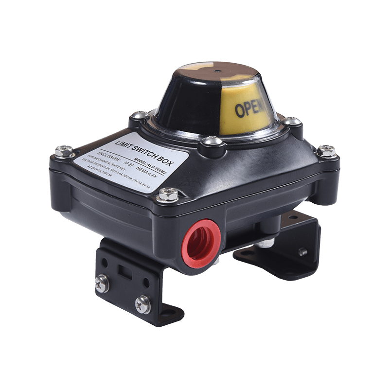 ALS Series Valve Position Limit SwitchCompact IP67 position indicator and switch box for valve automation, with explosion-proof variants, multiple sensor options, and NAMUR/ISO5211 mounting.View Product →
Cost, space and the total picture
Upfront price on its own misleads. At 2 inches, ball and gate valves sit in a similar band. The gap widens with bore size: a 12-inch gate valve is largely a casting with a simple wedge, while a 12-inch trunnion ball valve is a precision-machined assembly with matching seats. Gate designs also need more vertical space for a rising stem and, when automated, a heavier actuator with thrust capability.
Lifecycle flips the argument back. A valve cycled twice a year costs nothing in stroke time, so the gate design's slow travel is irrelevant. A valve cycled twice a shift puts labour and human error on the handwheel, and the quarter-turn valve wins on both counts.
For skid builders and OEMs, the rule that holds up is simple: standardise isolation on quarter-turn valves with a common mounting pad and a common gearbox family, and keep gate valves for the large-bore main isolation that is rarely touched. If you are weighing that trade-off for a specific project, contact our engineering team with the bore, media and cycle count and we will size the actuation around it.