

 en
 English
 Español

If a control valve must fail safe during a plant-wide power failure, a pneumatic positioner is often the only instrument that keeps the valve moving. Unlike electronic positioners that depend on stable power and clean signals, a pneumatic positioner runs on compressed air and a mechanical force balance. That simple fact explains why it remains the default choice in refineries, chemical plants, and remote pipeline stations. This article explains how a pneumatic positioner works, compares it with electro-pneumatic and digital alternatives, and gives practical selection and maintenance advice.
Content
- 1 What a Pneumatic Positioner Does
- 2 How It Works: Force Balance and Feedback
- 3 Types of Positioners: Pneumatic, Electro-Pneumatic, Digital
- 4 How to Select a Pneumatic Positioner
- 5 Common Applications and Industries
- 6 Maintenance and Troubleshooting Basics
- 7 Frequently Asked Questions
- 7.1 Q1: What is the difference between a pneumatic positioner and a pneumatic actuator?
- 7.2 Q2: How do you calibrate a pneumatic positioner?
- 7.3 Q3: Can a pneumatic positioner work with a digital control system?
- 7.4 Q4: What is the typical air supply pressure for a pneumatic positioner?
- 7.5 Q5: Why does my pneumatic positioner keep hunting?
- 7.6 Q6: What are the advantages of a pneumatic positioner over an electro-pneumatic one?
What a Pneumatic Positioner Does
A pneumatic positioner is a valve accessory that receives a pneumatic control signal, usually 3-15 psi or 0.2-1.0 bar, and adjusts the air pressure sent to a valve actuator. Its job is to make the valve stem position match the command signal, even when friction, flow forces, or packing drag change the load. Without a positioner, a control valve actuator may still move, but its stroke will drift as the process pressure changes. With a positioner, the valve stem follows the signal more accurately and repeats that position consistently.
The positioner is typically mounted on a linear or quarter-turn actuator. For quarter-turn valves, such as butterfly valves and ball valves, a pneumatic positioner is often paired with a compact pneumatic actuator. For example, the 10-series pneumatic actuator from Hawks is designed for reliable quarter-turn operation and can be combined with a positioner for precise modulating control.
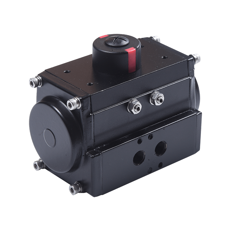 Hawks 10 Series Quarter-Turn Pneumatic ActuatorQuarter-turn pneumatic actuator for valve automation, available in double-acting and spring-return models with ISO5211, DIN3337 and Namur mounting for modulating control.View Product →
Inside the positioner, a feedback lever or cam connects to the actuator stem. As the stem moves, the feedback mechanism changes the force balance inside the positioner. This mechanical feedback is what separates a positioner from a simple volume booster.
How It Works: Force Balance and Feedback
Most pneumatic positioners use a force-balance principle. The input signal creates a force on a diaphragm or bellows. A range spring opposes that force. A nozzle-flapper assembly sits between them. When the forces are equal, the flapper stays at a fixed distance from the nozzle, and the output pressure to the actuator stays constant.
Signal Input and Nozzle Flapper
If the input signal increases, the diaphragm pushes the flapper closer to the nozzle. That restricts the air escaping from the nozzle, which raises the pressure in the relay. The relay then sends more air to the actuator, moving the valve stem. As the stem moves, the feedback cam or lever pulls the range spring or moves the flapper back. The system reaches a new balance when the valve position matches the new signal.
Feedback Cam and Range Spring
The feedback cam determines the relationship between stem rotation and spring force. A linear cam gives a linear characteristic; a modified cam can give equal percentage or quick-opening characteristics. The range spring sets the span, for example, 0.2-1.0 bar for a 90-degree quarter-turn valve. Zero adjustment shifts the starting point. These three elements—cam, spring, and zero screw—are the main calibration points.
The isometric sketch above labels the main mechanical parts. The exact layout varies by manufacturer, but the function is the same: compare signal force with feedback force, then adjust output pressure.
Types of Positioners: Pneumatic, Electro-Pneumatic, Digital
Positioners fall into three broad categories. Pneumatic positioners take a pneumatic input signal directly. Electro-pneumatic positioners convert an electrical signal, such as 4-20 mA, into a pneumatic output. Digital positioners use a microprocessor and often communicate over HART, Profibus, or Foundation Fieldbus. Each type has a different balance of accuracy, cost, and tolerance to harsh conditions.
| Type | Input Signal | Typical Accuracy | Best Use |
|---|---|---|---|
| Pneumatic | 3-15 psi or 0.2-1.0 bar | ±1% to ±2% of span | Hazardous areas, high vibration, simple loops |
| Electro-pneumatic | 4-20 mA | ±0.5% to ±1% of span | Distributed control systems, moderate accuracy |
| Digital | 4-20 mA + HART / fieldbus | ±0.1% to ±0.5% of span | High-accuracy loops, diagnostics, remote configuration |
Accuracy figures are typical ranges from manufacturer literature and industry guides; actual performance depends on actuator size, linkage, and calibration. For many on-off or coarse throttling applications, a pneumatic positioner is more than adequate. For fine chemical dosing or blending, a digital positioner may be worth the higher cost.
Figure 1: Typical accuracy ranges of positioner types (based on manufacturer datasheets and industry guides).
How to Select a Pneumatic Positioner
Actuator Compatibility and Torque
Selection starts with the actuator. A positioner must match the actuator’s stroke, rotation, and air volume. For quarter-turn valves, check the actuator torque output against the valve break torque, including safety factors for packing, flow, and pressure drop. A useful reference is this guide on calculating the required torque for a pneumatic actuator. If the actuator is undersized, no positioner can improve control; the valve will still hunt or stall.
Environmental and Safety Considerations
In explosive atmospheres, a pneumatic positioner has a clear advantage: it needs no electrical power and cannot create a spark. It also tolerates washdown, vibration, and wide temperature swings better than many electronic devices. For outdoor pipelines, specify a housing with the right ingress protection, such as IP66, and verify the air supply is clean and dry. Moisture and oil in the air supply are the most common causes of positioner failure.
Mounting and Feedback
Mounting hardware must be rigid. A loose bracket introduces backlash that no calibration can fix. Feedback is equally important. Limit switches provide remote position indication and can be used for alarm or interlock functions. The ALS-series limit switch from Hawks is a compact accessory for quarter-turn actuators and gearboxes, giving visual and electrical feedback without adding significant load to the stem.
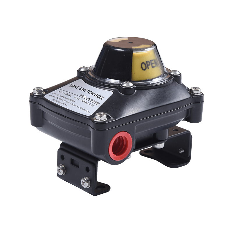 Hawks ALS Series Compact Limit Switch for Valve Position FeedbackCompact limit switch for quarter-turn actuators and gearboxes, offering visual/electrical feedback, IP67 and explosion-proof housing options for hazardous-area valve position indication.View Product →
Before installation, confirm the positioner’s cam rotation matches the actuator’s rotation direction. A cam installed for clockwise rotation will not work on a counterclockwise actuator without modification.
Common Applications and Industries
Pneumatic positioners appear wherever a control valve must operate reliably without complex electronics. Oil and gas production, refining, chemical processing, water treatment, and power generation all use them. In a typical refinery, you will find them on flow control valves, pressure control valves, and level control valves. In water treatment, they regulate flow through large butterfly valves. In remote gas stations, they work with solar-powered or pneumatic control loops where electricity is limited.
They also pair well with manual and declutch gearboxes. When a valve needs both automatic control and a manual override, a declutch part-turn gearbox can be combined with a pneumatic actuator and positioner. This arrangement allows operators to switch to manual operation during maintenance or air failure.
Maintenance and Troubleshooting Basics
Most pneumatic positioner problems trace back to air quality, linkage wear, or calibration drift. If the valve hunts, check for excessive packing friction, a loose feedback lever, or a worn cam. If the valve stops responding, inspect the nozzle for blockage and the relay for sticky parts. A regular maintenance schedule should include:
- Draining air filters and checking for oil carryover.
- Verifying supply pressure stays within the manufacturer’s range.
- Inspecting the feedback linkage for lost motion.
- Recalibrating zero and span after any actuator or valve work.
Keep a record of the original zero and span settings. When a positioner is replaced or serviced, returning to those settings reduces startup time and avoids process upsets.
Frequently Asked Questions
Q1: What is the difference between a pneumatic positioner and a pneumatic actuator?
A pneumatic actuator converts air pressure into mechanical force to open or close a valve. A pneumatic positioner receives a control signal and adjusts the air pressure to the actuator so the valve reaches a specific position. The actuator provides the muscle; the positioner provides the steering.
Q2: How do you calibrate a pneumatic positioner?
Calibration usually involves setting zero and span. Apply the minimum signal (e.g., 3 psi) and adjust the zero screw until the valve just starts to move. Apply the maximum signal (e.g., 15 psi) and adjust the span until the valve reaches full travel. Repeat until both endpoints are correct, then check mid-stroke linearity.
Q3: Can a pneumatic positioner work with a digital control system?
Yes, but you need an electro-pneumatic transducer or an I/P converter to change the 4-20 mA signal from the DCS into a pneumatic signal. A pure pneumatic positioner cannot accept a digital signal directly.
Q4: What is the typical air supply pressure for a pneumatic positioner?
Most pneumatic positioners use a supply pressure of 20 to 30 psi (1.4 to 2.0 bar) above the maximum output required by the actuator. A common supply is 40 psi (2.8 bar) for spring-return actuators, but always follow the manufacturer’s specification.
Q5: Why does my pneumatic positioner keep hunting?
Hunting is usually caused by excessive gain, air leakage, a loose feedback linkage, or oversized actuator volume. Check the nozzle and relay for dirt, verify the feedback cam is tight, and consider adding a volume booster if the actuator is large.
Q6: What are the advantages of a pneumatic positioner over an electro-pneumatic one?
A pneumatic positioner needs no electrical power, works in hazardous areas without intrinsic safety barriers, and tolerates high vibration and temperature. It is simpler and often lower in cost. Electro-pneumatic positioners offer better accuracy and easier integration with modern control systems.