

 en
 English
 Español

A 4-inch butterfly valve on a cooling-water header gets a new pneumatic actuator. On the bench it strokes in under two seconds. On the line it stalls halfway. Nothing is broken: the plant air runs at 4 bar rather than the 5.5 bar behind the catalogue torque figure, and the valve's breakaway torque after a season of deposits is roughly twice its clean running torque. The package was never sized as a system.
That is normally what people mean by an actuator valve: not the actuator on its own, but the valve, the operator and the interface between them. The definition is simple — a valve actuator is the mechanism that opens and closes a valve, driven by hand, air, oil or electricity. Making it work reliably comes down to three decisions, taken in this order: the mounting interface, the torque margin, and the fail-safe behaviour. Drive type is the last question, not the first.
Content
- 1 The mounting interface comes before the datasheet
- 2 Drive types: what each one is actually good at
- 3 Torque: the number that decides pass or fail
- 4 Manual override and what happens when the air stops
- 5 Position feedback and commissioning
- 6 Housings, corrosion and site conditions
- 7 What to put on the purchase order
- 8 Where these packages do the work
- 9 Frequently asked questions
- 9.1 What is the difference between a valve actuator and a valve positioner?
- 9.2 How do I calculate the torque needed for a butterfly valve actuator?
- 9.3 Can a pneumatic actuator be operated by hand during an air failure?
- 9.4 What does ISO 5211 F07 mean on a mounting flange?
- 9.5 What IP rating does an outdoor valve actuator need?
- 9.6 What is a part-turn gearbox used for?
The mounting interface comes before the datasheet
Motion type is the first filter. Butterfly and ball valves need 90 degrees of rotation; gate and globe valves need many turns of the stem. Putting a quarter-turn actuator on a multi-turn stem is not a torque problem, it is a geometry problem, and no amount of sizing fixes it.
The mechanical connection is standardised. ISO 5211 defines flange sizes — F05, F07, F10, F12 and upward — together with bolt circles and drive forms such as square, star and keyed bores. Adapter plates and stem bushes let mismatched parts work together, and they are common in the field. But every adapter adds stack height, a little backlash, and one more component that can be fitted the wrong way round. When valve and operator share a flange standard, assembly is a bolt-up job with a short, predictable torque path.
Worth checking early: ISO 5211 mounting components and the real stem dimensions. Measuring the stem takes two minutes; finding the mismatch mid-shutdown takes considerably longer.
Drive types: what each one is actually good at
Once the interface is settled, the choice is mostly about what the site can supply and how often the valve has to move.
| Drive type | Power source | Where it wins | What to watch |
|---|---|---|---|
| Hand lever | Manual | Small butterfly valves, isolation duty, no services on site | Torque limited by the operator; not repeatable |
| Manual part-turn gearbox | Manual | Larger valves; worm ratio multiplies effort from 20:1 upward | Slow operation; handwheel clearance needed |
| Pneumatic | Compressed air | On/off and fail-safe duty, fast cycling, hazardous areas | Output torque falls with supply pressure |
| Electric | Mains or 24 V | Modulating control, no air header, remote indication | Higher cost; needs power and control wiring |
| Hydraulic | Hydraulic power pack | Very high torque, heavy shock loads, subsea | Oil leakage risk; needs a power unit |
In practice most plants choose between pneumatic and electric. A pneumatic unit is cheap per newton-metre, cycles fast, tolerates dirty and hazardous areas, and with a spring return it fails to a known position when air is lost. Electric actuation costs more up front but suits modulating duty, reports position without extra switches, and does not depend on an air header that may be at 4 bar on a cold morning. Hydraulic units are usually reserved for very high torque or heavy shock loads.
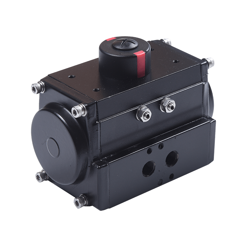 10-Series Pneumatic Rack-and-Pinion Valve ActuatorDouble-acting and spring-return quarter-turn actuator with ISO 5211 and NAMUR mounting, suited to direct valve automation and accessory installation.View Product →
Where the plant already has dry instrument air, a matched quarter-turn operator such as the 10-series pneumatic actuator removes most of the commissioning questions — the flange, the drive and the stroke are settled before the valve reaches the pipe rack.
Torque: the number that decides pass or fail
Valve torque is not one figure. Running torque is what the valve needs once it is moving. Breakaway torque is what it needs to leave the seat, and it is always the larger of the two — on a valve that has seen service, two to three times larger is not unusual, because deposits, seat compression and differential pressure all resist the first few degrees of travel.
Sizing therefore starts from breakaway torque at the worst differential pressure the line can produce, with a margin on top. A factor of 1.3 to 1.5 is common industry practice; go higher where the medium is dirty or the valve is rarely cycled.
The other half of the calculation is what the actuator actually delivers. A double-acting pneumatic actuator's output is close to proportional to supply pressure, so the torque printed in a catalogue is only valid at the pressure it was rated at.
That is the stall in the opening example. An actuator rated 100 N·m at 5.5 bar delivers about 73 N·m at 4 bar. Spring-return units lose return torque the same way and should be checked in the fail direction, not just the power stroke. Temperature derating matters too: most makers publish a reduced torque curve above roughly 60 degrees C ambient.
Manual override and what happens when the air stops
Fail-safe behaviour has to be decided before the actuator is ordered. A spring-return unit drives the valve to a known position when air or power fails, which is why it dominates isolation duty. A double-acting unit holds its last position, which suits processes where moving the valve is worse than leaving it where it is.
Overriding that decision by hand is where declutch gearboxes earn their place. Pull the lever and the worm disengages, so the handwheel drives the stem directly with no fight from the gearing; push it back and normal control resumes without removing the actuator or breaking the mounting seal. On a packaged plant that is the difference between a ten-minute intervention and a planned shutdown.
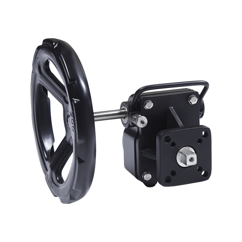 GD-Series Aluminium Declutch Part-Turn GearboxCompact declutch gearbox for pneumatic-actuated butterfly, ball and plug valves, enabling manual operation during setup or air loss with ISO 5211 mounting and IP65 protection.View Product →
The GD-series aluminium declutch part-turn gearbox is a typical example of the pattern: handwheel for manual duty, clutch lever for fast changeover, and a flange pattern that keeps the actuator stack short.
Position feedback and commissioning
Limit switches confirm end positions to the control room, interlock pumps, or trigger alarms. Mechanical SPDT switches remain the most common choice for on/off duty; proximity types suit high-cycle or vibration-heavy installations. Two details decide whether the feedback can be trusted: the cams must be set after the valve has been stroked against real line conditions rather than on the bench, and the enclosure has to match the environment — IP65 indoors, IP67 where washdown or weather is involved.
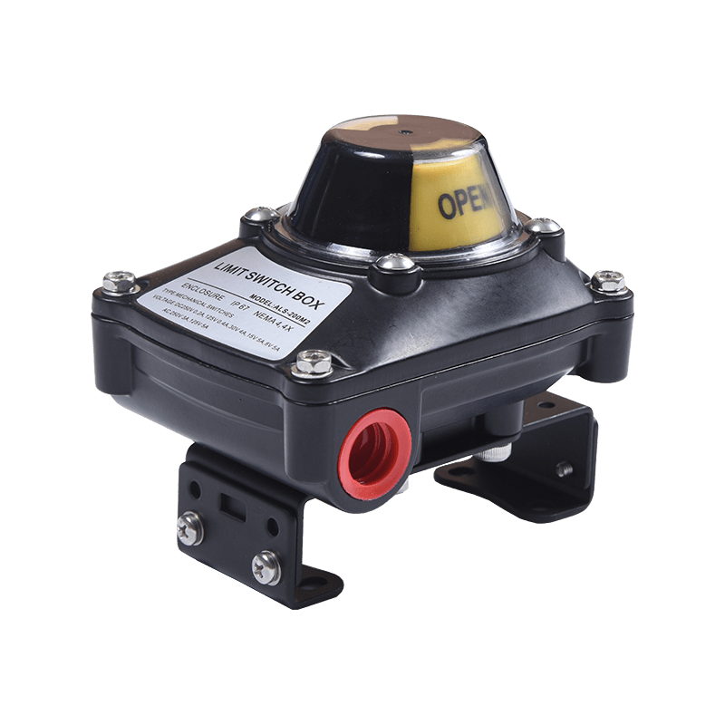 ALS-Series Valve Position Limit Switch BoxCompact valve-position feedback unit with mechanical, inductive or magnetic sensors, IP67 protection and explosion-proof options for industrial and hazardous-area limit switching.View Product →
An ALS-series limit switch box is normally specified together with the gearbox rather than afterwards, because the mounting bracket and shaft extension are far easier to match at the ordering stage.
Housings, corrosion and site conditions
Aluminium housings keep weight and cost down on small and medium part-turn units, and take well to coating for coastal or chemical atmospheres. Cast iron is heavier and stiffer, and is often preferred on large double-stage gearboxes where torque is high and the mounting is permanent. Seals are the quieter issue: standard nitrile compounds cover water and most industrial air, but high-temperature or aggressive media usually need a different compound, and the ambient range in the datasheet should be read as a limit rather than a suggestion.
What to put on the purchase order
- Motion type and valve size, with the ISO 5211 flange and stem dimensions measured rather than assumed.
- Breakaway torque at the worst-case differential pressure, plus the safety factor used to reach the selection target.
- Air supply pressure range on site, not just the nominal figure, along with any air quality requirement.
- Fail-safe direction — fail closed, fail open or hold — and the return torque available in that direction.
- Position feedback type, switch rating and required enclosure IP rating.
- Ambient temperature, corrosion class, and any hazardous-area certification the site demands.
A missing item on this list rarely shows up at goods-in. It shows up on the night shift, when the valve will not stroke and nobody can tell whether the problem is the actuator, the air supply or the valve itself.
Where these packages do the work
Water and wastewater plants cycle valves constantly and depend on repeatable position feedback. HVAC chilled-water systems favour compact quarter-turn packages that fit inside plant rooms. Food and beverage lines need washdown-rated housings and frequent stroking for cleaning cycles. Chemical and power plants put the emphasis on fail-safe behaviour and torque margin under abnormal differential pressure. The thread running through all of them is that the operator is selected as part of a control chain rather than as a standalone accessory — which is the thinking behind these industrial valve control solutions.
Frequently asked questions
What is the difference between a valve actuator and a valve positioner?
The actuator moves the valve; the positioner controls how far it moves. A positioner compares a control signal with actual stem position and adjusts the air supply, which matters for modulating duty and is unnecessary for simple open/close service where limit switches are enough.
How do I calculate the torque needed for a butterfly valve actuator?
Start with the valve maker's breakaway torque at the highest differential pressure expected, add a 1.3 to 1.5 safety factor, then check the actuator's output at the lowest air pressure on site instead of the rated figure. Seat material and solids in the medium change the result considerably.
Can a pneumatic actuator be operated by hand during an air failure?
With a spring-return unit the valve travels to its fail position automatically. For anything else, a declutch gearbox or a top-mounted handwheel lets an operator drive the stem manually without dismantling the actuator.
What does ISO 5211 F07 mean on a mounting flange?
It is a flange size within the ISO 5211 standard, fixing bolt circle, bolt size and spigot dimensions so actuators and valves from different makers can be bolted together. F07 is common on small and medium quarter-turn valves.
What IP rating does an outdoor valve actuator need?
IP67 covers rain, hose-down and short immersion, and is the usual minimum outdoors. Indoor plant rooms are generally served by IP65. The rating applies to the whole enclosure, so check cable glands and covers as well.
What is a part-turn gearbox used for?
It multiplies manual effort on quarter-turn valves — typically 20:1 and upward on a single-stage worm unit — so a large butterfly or ball valve can be turned by one person. Declutch versions add a handwheel that takes over from the actuator.